

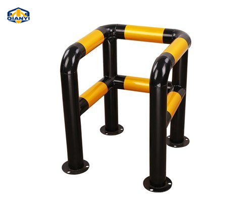
 Equipment protection guards
Products
Equipment protection guards
 1 / 4
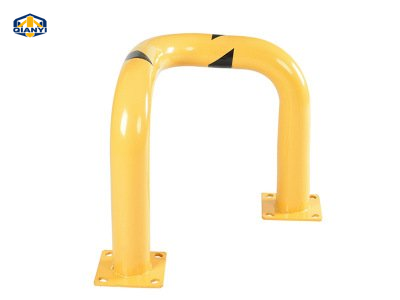
Tripod-elbow steel corner guard reference.
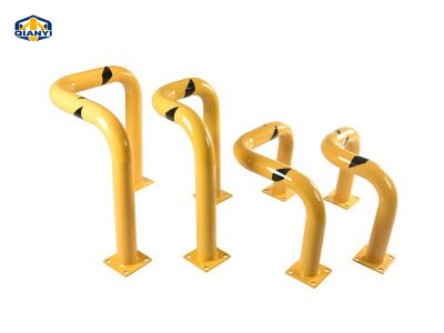
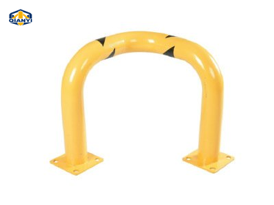
Reference photographs show the selected assembly. Confirm dimensions, cap, mounting and finish against the agreed drawing. The dimension reference is not a fabrication drawing.
QY-SR07
Tripod-elbow steel equipment corner guard
A flanged steel corner-guard assembly for equipment and building edges, offered with two separately listed height and width references.
Key Features
- Tripod-elbow layout
- Steel corner guard
- Flange bases
- Surface-mounted flange bases
Model 3 reference series
Compare each complete assembly. Sizes and hardware belong to the individual reference series.
Download Specification & range files
Reference files for quotation. An approved product drawing is agreed separately.
Product Details
Description
A flanged steel corner-guard assembly for equipment and building edges, offered with two separately listed height and width references.
Individual posts and open frames need a layout around the equipment they accompany. Review clearances with the equipment drawing before setting the fixing points.
- Equipment doors, panels and service space
- Post or guard outline and installation method
- Cable routes, user access and fixing positions
Confirm the selected factory cap profile, original colour, joining and finishing method, and any handle or ring against the assembly drawing. The pictured configuration and the reference specification should be reviewed together.
Product Specifications
Reference configurations for quotation. Final dimensions, materials and supply are subject to drawing and quotation confirmation.
| Reference model | Height (mm) | Width (mm) | Tube Ø (mm) | Wall (mm) | Base (mm) | Net weight (kg) |
|---|---|---|---|---|---|---|
| HQ-114BS-W101 | 610 | 610 | 114; confirm diameter | 2.75 | 200 × 200 × 8 | Size pairing to confirm |
| HQ-114BS-W101 | 610 | 762 | 114; confirm diameter | 2.75 | 200 × 200 × 8 | Size pairing to confirm |
| Item | Reference configuration |
|---|---|
| Material reference | Steel pipe with carbon steel flange bases. |
| Size references | 610 mm height × 610 mm width, or 610 mm height × 762 mm width |
| Tube reference | Ø114 × 2.75 mm wall in the configuration table; diameter to agreed drawing |
| Flange base | 200 × 200 × 8 mm carbon steel; hole layout to drawing |
| Net weight references | 4.6 / 5.6 kg; size-to-weight pairing to confirm |
| Finish and packing | Powder coating, black reflective detailing; one piece per carton |
| Marking references | 5 mm reflective-film width and 50 mm sticker width are separate references; confirm the selected marking layout. |
Dimensions from different reference assemblies should not be combined without confirmation. The approved drawing defines the supplied assembly and installation details.
Detail media
Reference photographs show the selected assembly. Confirm dimensions, cap, mounting and finish against the agreed drawing.
Points to confirm
01Choose one height and width reference for the corner layout.
02Confirm tube diameter, the complete three-dimensional layout and the matching weight on the agreed drawing.
Compare Reference Series
Similar formats can have different materials, sections and mounting assemblies.
| Reference series | | | 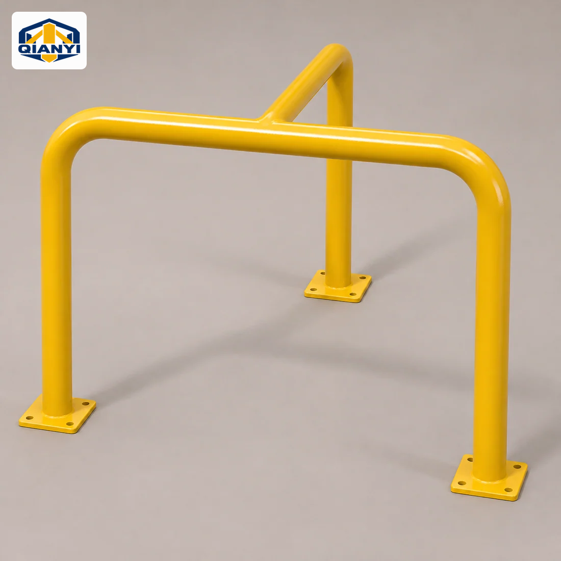 | 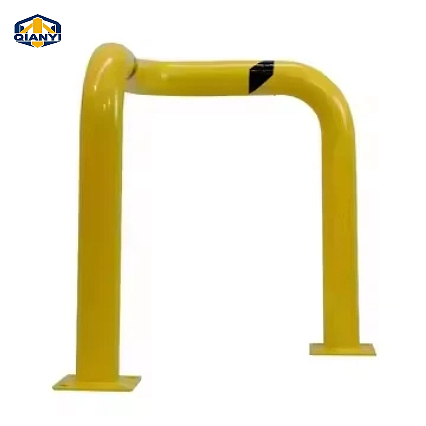 |
|---|---|---|---|---|
| Reference size | 610 mm height · 610 / 762 mm width | 500 × 500 × 600 mm | Ø60 mm tube · frame size to drawing | Custom corner layout · dimensions to drawing |
| Material reference | Steel pipe with carbon steel flange bases. | Steel pipe. The main FHSC001 technical configuration specifies a 76 mm tube and a 3 mm wall; related layouts require their own tube confirmation. | Proposed steel fabrication; grade, wall thickness and finish to the approved frame drawing. | Steel; grade and corrosion-protection system to the agreed drawing. |
| Mounting / operation | Surface-mounted flange bases | Bolt down on individual flange feet; anchor layout to approved drawing | Surface mounted or embedded; to drawing | Mounting feet and fixing layout to drawing |
| Base / receiving assembly | Flange base: 200 × 200 × 8 mm carbon steel; hole layout to drawing | Feet and finish: Confirm footplate dimensions, fixing centres, coating and reflective bands | Feet and finish: Mounting, corrosion protection and colour to drawing | Confirm the complete mounting assembly in the drawing. |
| Structure details | Tripod-elbow layout · Steel corner guard · Flange bases | Welded steel frame · Individual flange feet · 500 mm square footprint · Single or double rail layout | Three-leg frame · Open equipment clearance · Drawing required | Welded steel guard · Equipment-corner reference · Mounting feet |
Compare complete assemblies. Dimensions, materials and mounting details require drawing and quotation confirmation; no stock or impact rating is implied.
Application References
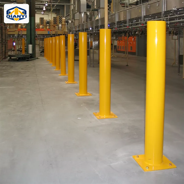
Factories, warehouses & loading bays
Define equipment edges, loading entrances and vehicle routes around the way the warehouse operates.
View planning considerations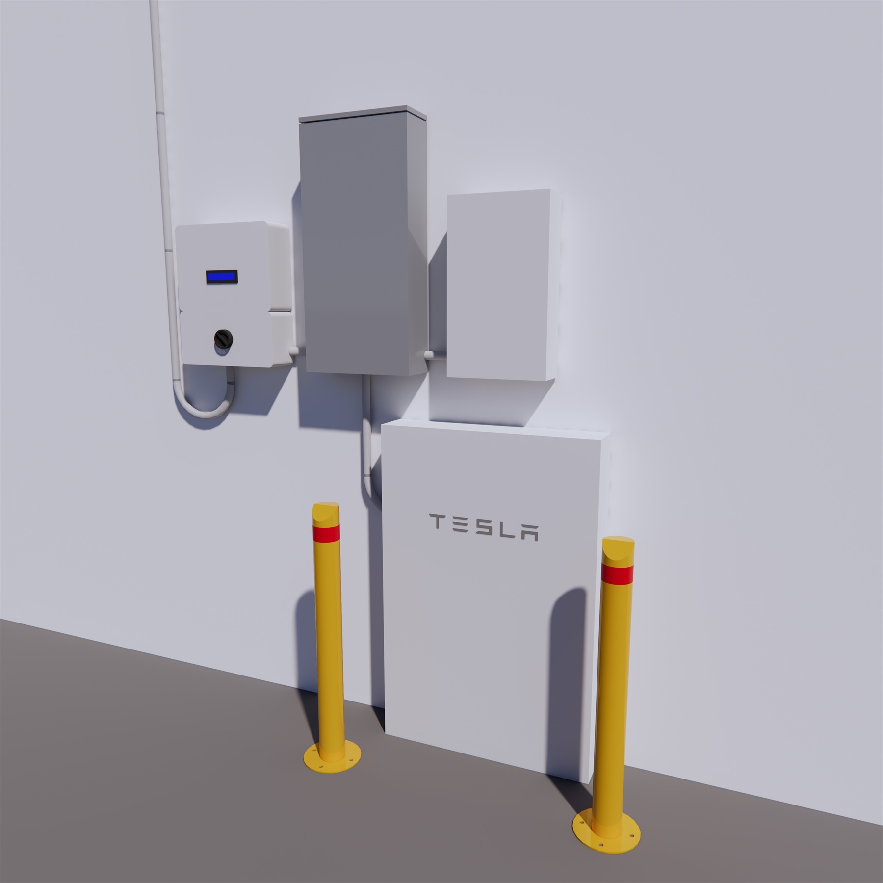
EV charging & battery equipment
Develop post and guard layouts around equipment envelopes, charging cables and maintenance clearances.
View planning considerations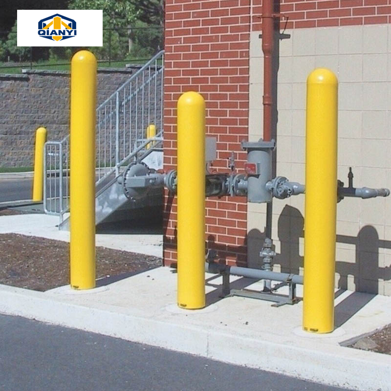
Industrial equipment & pipework
Compare individual posts and low or tall guards around machinery, pipework and service equipment.
View planning considerationsSupplier reference image · not a verified Qianyi project or a site-layout drawing.
Related Products
View all Equipment protection guardsFrequently Asked Questions
Can a guard be sized around a specific cabinet or charger?
Send the equipment outline and its required access, ventilation and maintenance spaces. The post or open-frame layout can then be discussed against the equipment and installation drawing.
Can you review a different size or finish?
Send your drawing or the required section, height, wall, mounting detail and finish. Custom configurations are reviewed against the agreed specification; final supply details follow the quotation and approved drawing.
Are fixings, locks and other accessories included?
The itemised quotation defines what is supplied. List any anchors, sleeves, covers, locks, keys or other hardware you need rather than assuming that every accessory shown in a reference image is included.
What should I send for a useful quotation?
Include QY-SR07, quantity, the complete dimensions, material and finish, installation method, drawing revision and destination. Add packing, labelling, sample and any required testing documents so the same configuration can be reviewed.
Contact & Enquiry
Discuss your configuration
Send the drawing, quantity and destination for your selected assembly, or add this series to a mixed-product enquiry list.
- Product reference
- QY-SR07
- Reference dimensions
- 610 mm height · 610 / 762 mm width
- qianyi0576@163.com
- +86 150 5764 7645
Contact links open a draft for you to review and send. Drawing, supply and commercial details are confirmed in the quotation.
Review your multi-product enquiry