

 U-shaped protection guards
QY-BP07
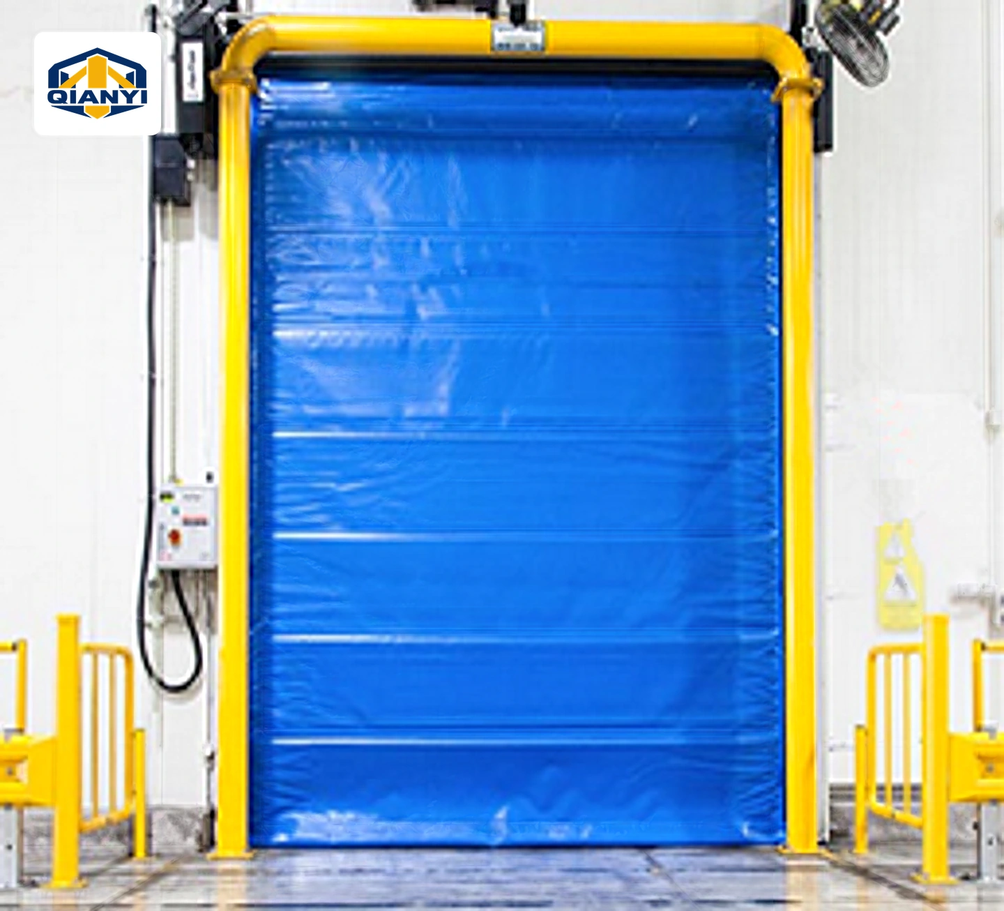
Modular steel doorway protection frame
Clear opening H × W: 3000 × 2800 to 5200 × 3000 mm
Products
 1 / 3
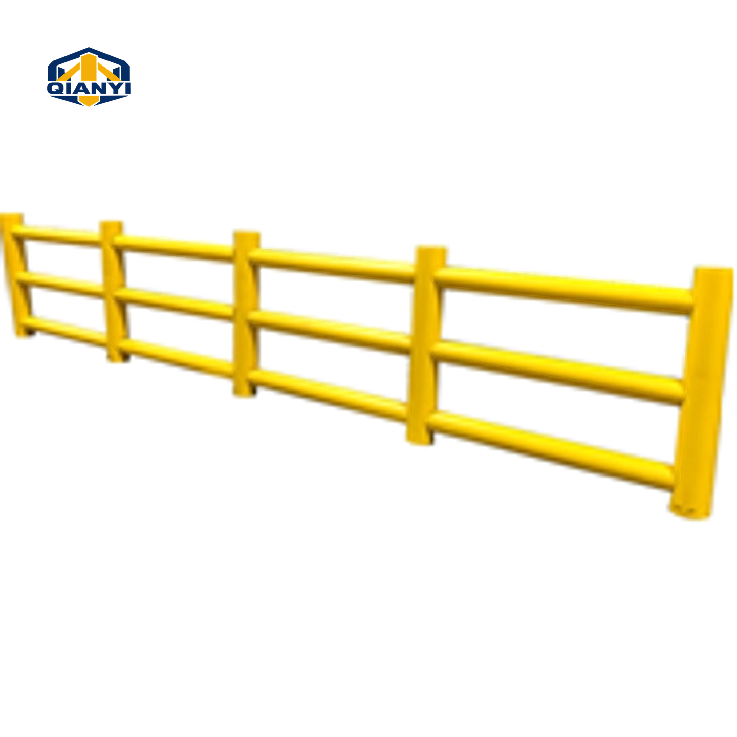
Digitally restored reference image of the steel bollard-and-rail system. Dimensions follow the agreed drawing.
Reference photographs show the pictured steel assembly. Confirm the selected dimensions, mounting, original cap and finish against the agreed drawing. The dimension reference is not a fabrication drawing.
QY-BP12
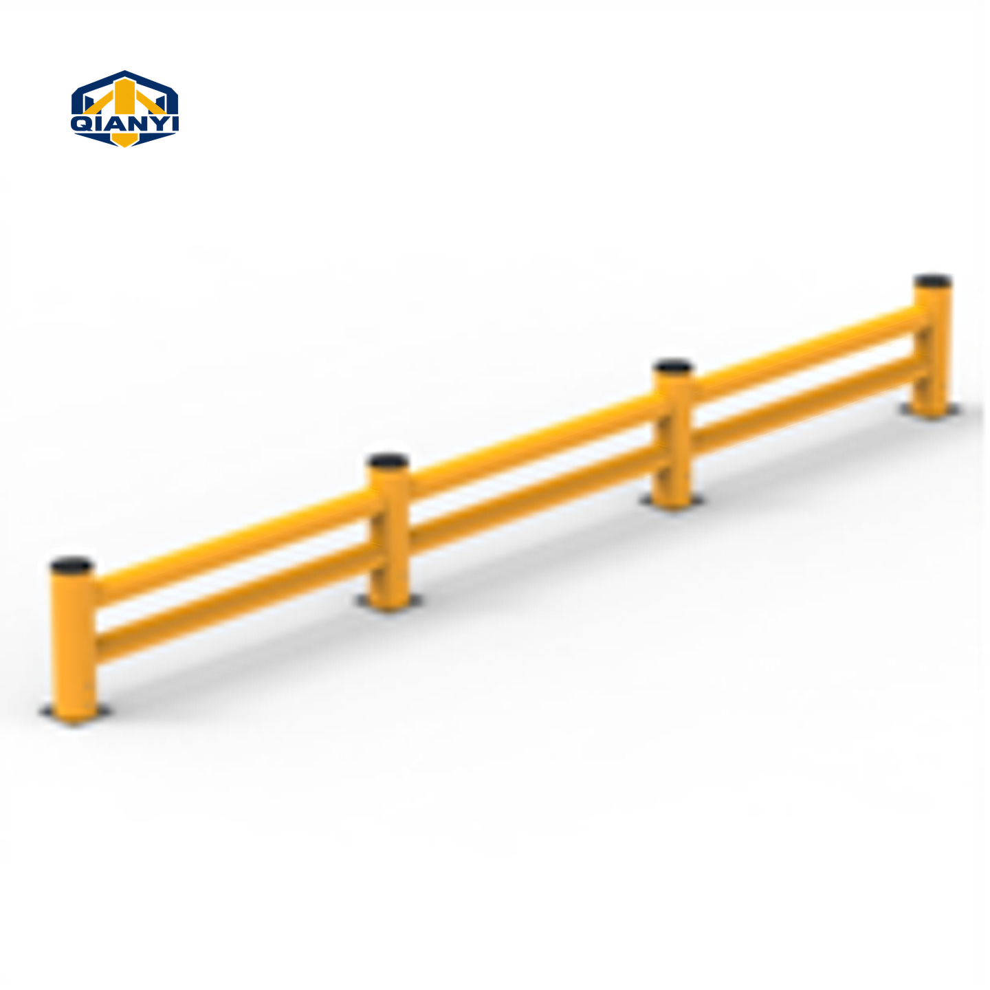
A steel post-and-rail system with several post-height and rail-length references. Specify the connections, bases and complete layout for the traffic route being separated.
Compare each complete assembly. Sizes and hardware belong to the individual reference series.
Reference files for quotation. An approved product drawing is agreed separately.
A steel post-and-rail system with several post-height and rail-length references. Specify the connections, bases and complete layout for the traffic route being separated.
Overall width and clear working space describe different dimensions. Show the equipment outline, bends, feet and access requirements in the same guard drawing.
Confirm the selected factory cap profile, original colour, joining and finishing method, and any handle or ring against the assembly drawing. The pictured configuration and the reference specification should be reviewed together.
Reference configurations for quotation. Final dimensions, materials and supply are subject to drawing and quotation confirmation.
| Parameter | Published reference | Configuration review |
|---|---|---|
| Steel reference | ASTM A1011 stated by source | Material grade for Qianyi supply to quotation; no certification asserted |
| Post heights | 18 / 27 / 36 / 42 / 43 in | 457.2 / 685.8 / 914.4 / 1066.8 / 1092.2 mm exact conversions |
| Rail lengths | 2–10 ft | 609.6–3048 mm reference range; complete layout to drawing |
| Finish | Yellow powder coating | Coating system to quotation |
| Hardware | Source mentions hardware | Exact fixing and joint set to confirm |
| Item | Reference configuration |
|---|---|
| Material reference | Steel; grade and corrosion-protection system to the agreed drawing. |
| Steel reference | ASTM A1011 stated by source |
| Post heights | 18 / 27 / 36 / 42 / 43 in |
| Rail lengths | 2–10 ft |
| Finish | Yellow powder coating |
| Hardware | Source mentions hardware |
Dimensions from different reference assemblies should not be combined without confirmation. The approved drawing defines the supplied assembly and installation details.
Reference photographs show the pictured steel assembly. Confirm the selected dimensions, mounting, original cap and finish against the agreed drawing.
01Agree the full section, mounting arrangement and finish for the chosen assembly.
02Published options are references for quotation; each supplied assembly follows its agreed drawing.
Similar formats can have different materials, sections and mounting assemblies.
| Reference series | | | 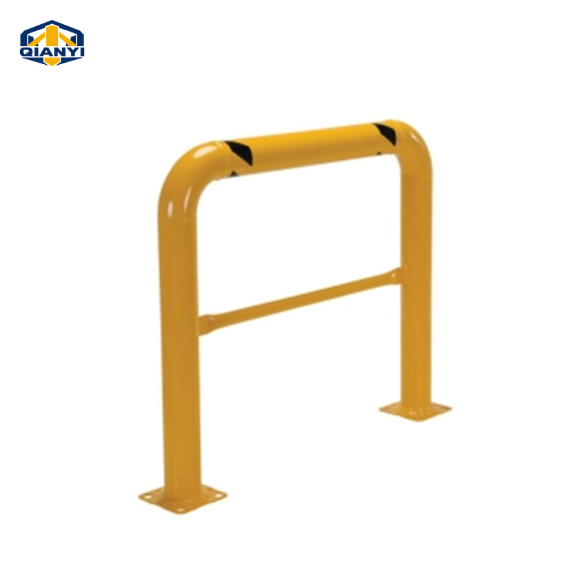 | 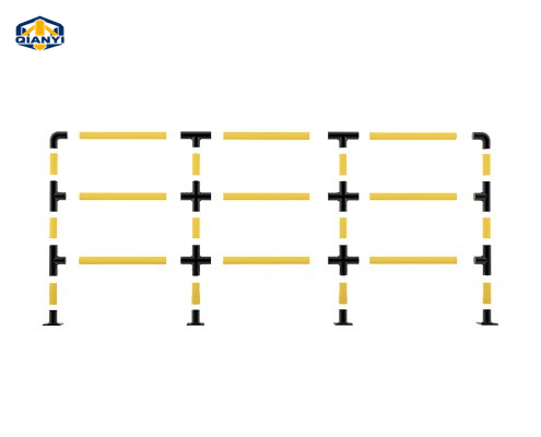 |
|---|---|---|---|---|
| Reference size | 18 / 27 / 36 / 42 / 43 in posts · 2–10 ft rail references | Clear opening H × W: 3000 × 2800 to 5200 × 3000 mm | 24 / 36 / 42 / 48 in height · 36 / 48 in width references | 300 / 600 / 900 mm barrier heights · 1050 mm length references |
| Material reference | Steel; grade and corrosion-protection system to the agreed drawing. | Steel; grade and corrosion-protection system to the agreed drawing. | Steel; grade and corrosion-protection system to the agreed drawing. | Steel pipe with ABS connecting joints. |
| Mounting / operation | Base and joint assembly to selected drawing | Bolted modular assembly with flanges and base plates | Surface mounted with anchor bolts | Detachable flange bases |
| Base / receiving assembly | Confirm the complete mounting assembly in the drawing. | Confirm the complete mounting assembly in the drawing. | Base plate references: 6 × 6 / 8 × 8 in | Component base reference: 70 × 55 mm detachable flange; thickness and fixings to drawing. |
| Structure details | Steel post-and-rail assembly · Height and rail options · Fixings to drawing | Modular doorway frame · Flanged connections · Three-piece construction | U-shaped steel tube · Two flange feet · Section and bend to drawing | Modular steel barriers · ABS elbow and T-joints · Assembled and component options · Detachable bases |
Compare complete assemblies. Dimensions, materials and mounting details require drawing and quotation confirmation; no stock or impact rating is implied.
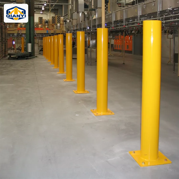
Define equipment edges, loading entrances and vehicle routes around the way the warehouse operates.
View planning considerations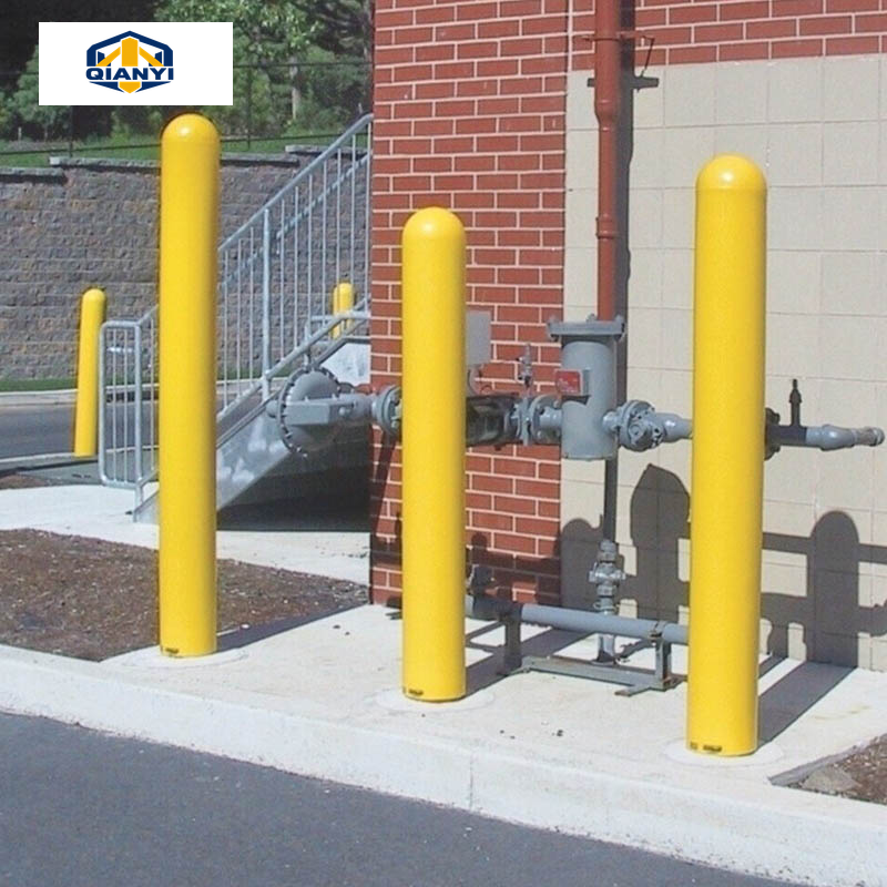
Compare individual posts and low or tall guards around machinery, pipework and service equipment.
View planning considerations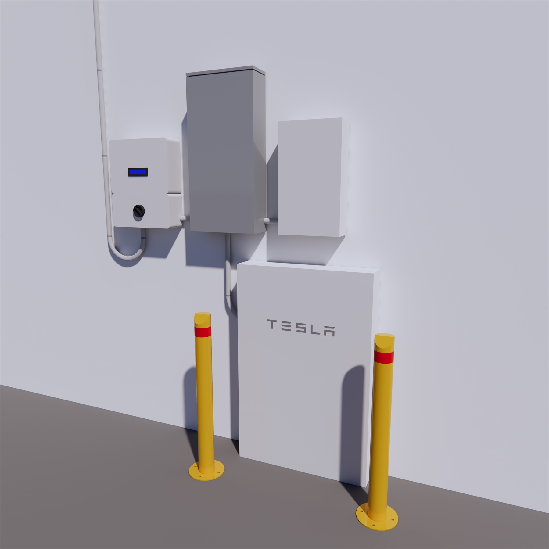
Develop post and guard layouts around equipment envelopes, charging cables and maintenance clearances.
View planning considerationsSupplier reference image · not a verified Qianyi project or a site-layout drawing.
U-shaped protection guardsClear opening H × W: 3000 × 2800 to 5200 × 3000 mm
U-shaped protection guards24 / 36 / 42 / 48 in height · 36 / 48 in width references
U-shaped protection guards300 / 600 / 900 mm barrier heights · 1050 mm length references
Confirm the measuring points on the guard drawing. Overall width, tube centre spacing and clear opening are different dimensions, and the equipment must fit within the agreed usable space.
Send your drawing or the required section, height, wall, mounting detail and finish. Custom configurations are reviewed against the agreed specification; final supply details follow the quotation and approved drawing.
The itemised quotation defines what is supplied. List any anchors, sleeves, covers, locks, keys or other hardware you need rather than assuming that every accessory shown in a reference image is included.
Include QY-BP12, quantity, the complete dimensions, material and finish, installation method, drawing revision and destination. Add packing, labelling, sample and any required testing documents so the same configuration can be reviewed.
Send the drawing, quantity and destination for your selected assembly, or add this series to a mixed-product enquiry list.
Contact links open a draft for you to review and send. Drawing, supply and commercial details are confirmed in the quotation.
Review your multi-product enquiry