

 Removable bollards
QY-RMSLEEVE90
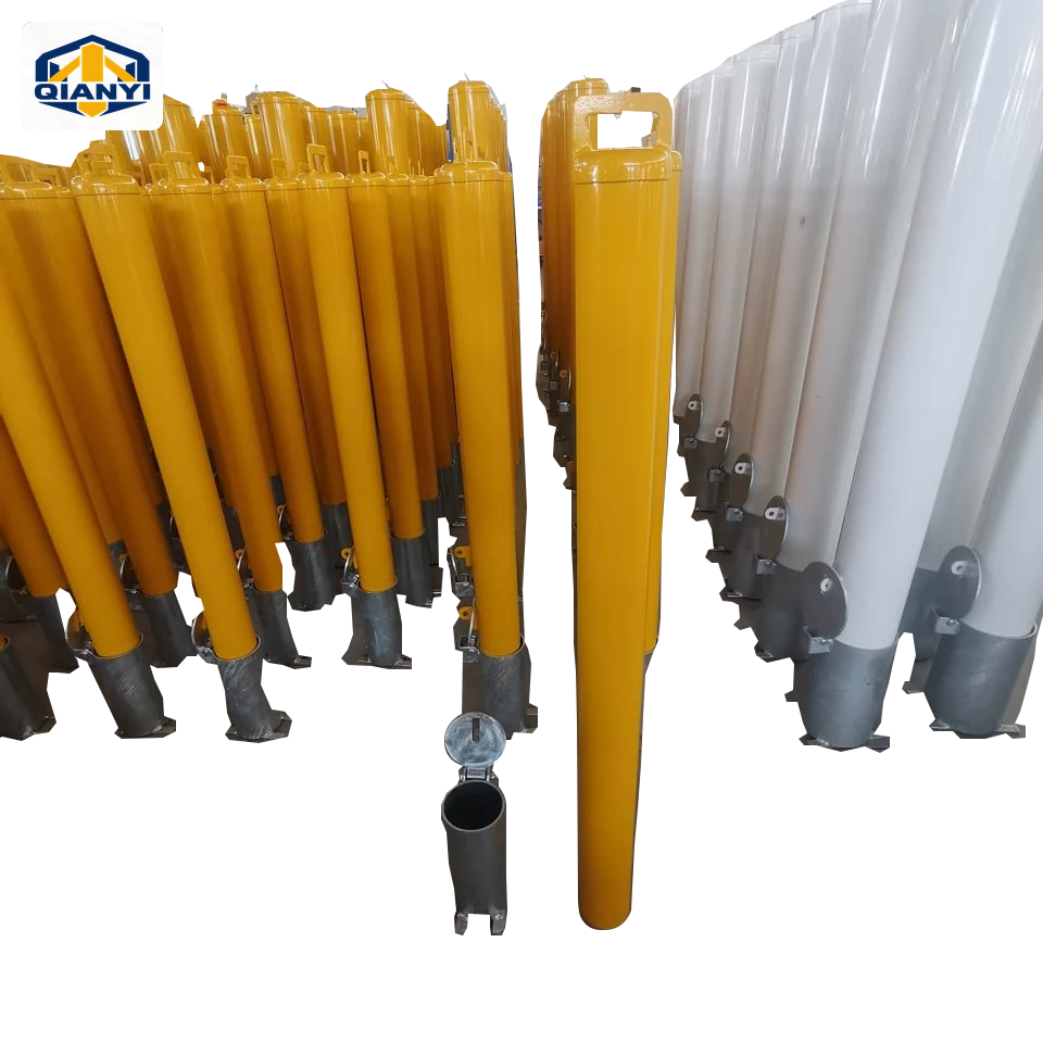
90 mm padlock sleeve-removable bollard
Ø90–140 mm · 960 / 1000 mm exposed height references
Products
 1 / 3
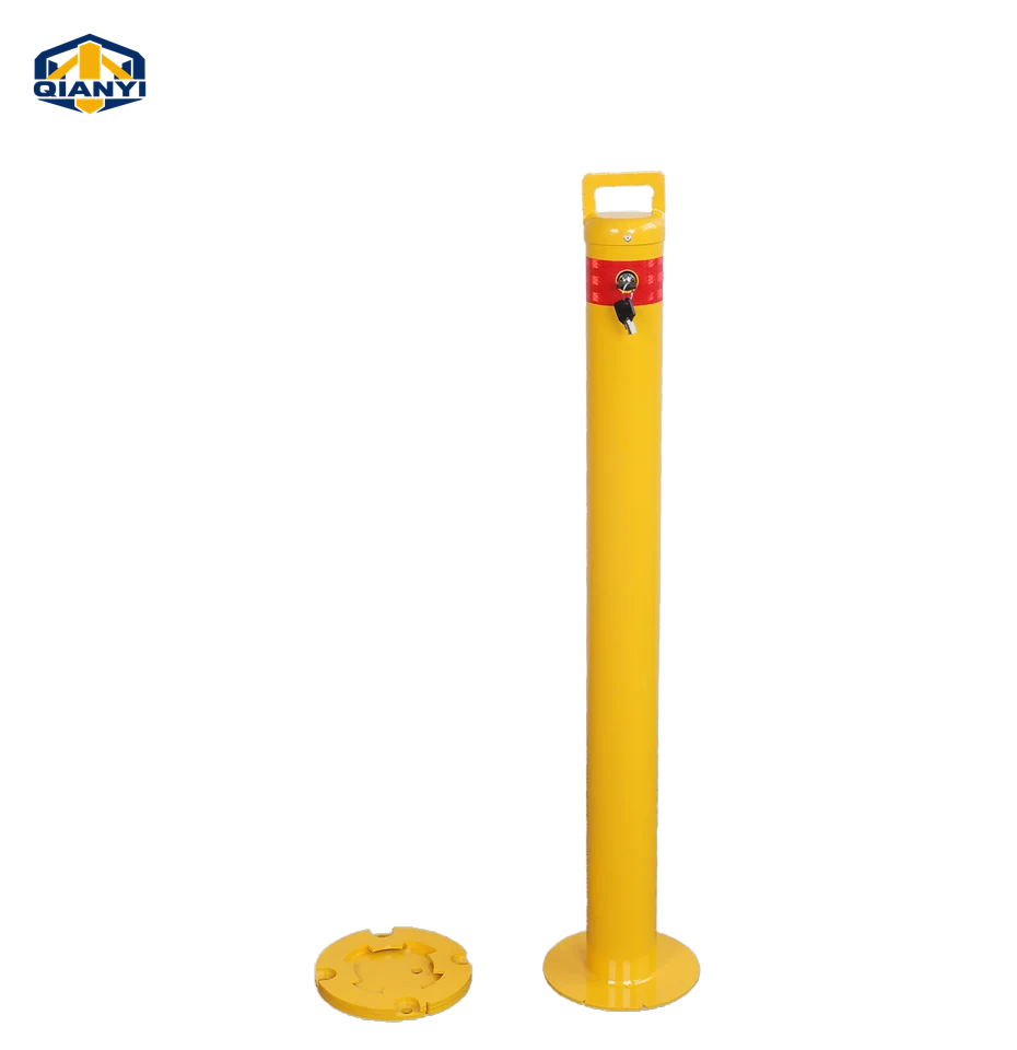
Supplier reference image · Surface-shoe removable steel post. Ø89 supplier reference assembly with a surface-mounted receiving shoe. Confirm shoe footprint, lock and lifting handle together.
Original supplier images retain the pictured cap construction, factory colour, base and hardware. Ø89 supplier reference assembly with a surface-mounted receiving shoe. Confirm shoe footprint, lock and lifting handle together. The catalogue dimensions describe the quoted reference series; confirm the complete assembly against the order drawing. The dimension reference is not a fabrication drawing.
QY-RMBASE90
A lift-out post with a circular surface-mounted locking shoe.
Compare each complete assembly. Sizes and hardware belong to the individual reference series.
Reference files for quotation. An approved product drawing is agreed separately.
A lift-out post with a circular surface-mounted locking shoe.
Review the receiving shoe or sleeve, the locking arrangement and what remains at ground level together with the lift-out post.
Confirm the selected factory cap profile, original colour, joining and finishing method, and any handle or ring against the assembly drawing. The pictured configuration and the reference specification should be reviewed together.
Reference configurations for quotation. Final dimensions, materials and supply are subject to drawing and quotation confirmation.
| Item | Reference configuration |
|---|---|
| Material reference | Galvanised steel; yellow-coated reference finish. |
| Tube reference | Ø90 mm with a 2–4 mm wall |
| Height reference | 1000 mm catalogue height; post and installed assembly heights to be defined |
| Round shoe A | Ø200 mm; 20 mm reference shoe height; plate thickness to approved drawing. |
| Round shoe B | Ø165 mm; plate thickness to approved drawing. |
| Lock reference | Integrated key lock; keyed-alike option to be confirmed |
Dimensions from different reference assemblies should not be combined without confirmation. The approved drawing defines the supplied assembly and installation details.
Original supplier images retain the pictured cap construction, factory colour, base and hardware. Ø89 supplier reference assembly with a surface-mounted receiving shoe. Confirm shoe footprint, lock and lifting handle together. The catalogue dimensions describe the quoted reference series; confirm the complete assembly against the order drawing.
01Choose the round-shoe design and define the surface remaining after removal.
02Confirm cap, lifting arrangement and lock-cylinder specification.
03Specify shoe height and steel plate thickness as separate dimensions.
04Retain the selected factory cap profile, colour, handle and ring. Confirm whether the assembly uses a fitted cap or a welded, ground-smooth closure; reflective-band height is specified separately.
Similar formats can have different materials, sections and mounting assemblies.
| Reference series | | | 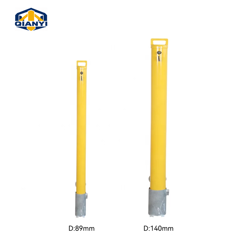 | 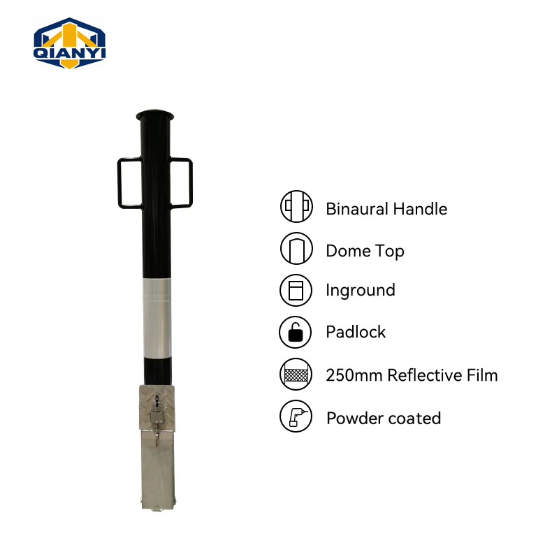 |
|---|---|---|---|---|
| Reference size | Ø90 × 1000 mm catalogue height | Ø90–140 mm · 960 / 1000 mm exposed height references | Ø90 × 950 mm exposed · 3–5 mm wall | Ø89 mm · 965 mm height reference |
| Material reference | Galvanised steel; yellow-coated reference finish. | Galvanised steel; yellow coating and red reflective-band references. | Galvanised steel; yellow powder-coated reference finish. | Q235 carbon steel. |
| Mounting / operation | Surface-mounted round locking shoe | In-ground receiving sleeve | In-ground sleeve; internal lock | Lift-out post and matched receiver |
| Base / receiving assembly | Round shoe A: Ø200 mm; 20 mm reference shoe height; plate thickness to approved drawing. · Round shoe B: Ø165 mm; plate thickness to approved drawing. | Receiving sleeve: Ø105 × 230 mm reference. Confirm the matching sleeve dimensions for the selected tube. · Hinged sleeve cover: One reference has 145 mm overall hinge width | Below-ground section reference: 200 mm; receiving assembly dimensions to drawing | Confirm the complete mounting assembly in the drawing. |
| Structure details | Lift-out post · Round shoe · Key lock | Ground sleeve · External padlock · 2–4 mm wall | Ground sleeve · Internal cam lock · 3–5 mm wall | Round steel tube · Lift-out post and matched receiver · Wall / tube options to table |
Compare complete assemblies. Dimensions, materials and mounting details require drawing and quotation confirmation; no stock or impact rating is implied.
Compare fixed boundaries, lift-out posts and fold-down parking posts around the access that the site needs.
View planning considerations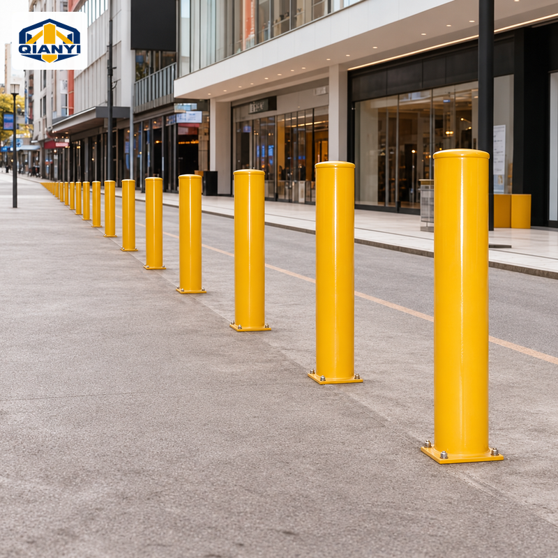
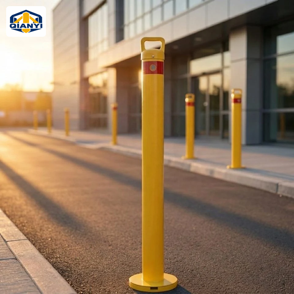
Plan shopfront edges and pedestrian routes with clear openings, consistent spacing and an agreed finish.
View planning considerationsSupplier reference image · not a verified Qianyi project or a site-layout drawing.
Removable bollardsØ90–140 mm · 960 / 1000 mm exposed height references
Removable bollardsRemovable bollardsCompare the available fixing surface, ground conditions, required clear opening and what may remain when the post is removed. Confirm the shoe or sleeve, cover, drainage and lock together.
Send your drawing or the required section, height, wall, mounting detail and finish. Custom configurations are reviewed against the agreed specification; final supply details follow the quotation and approved drawing.
The itemised quotation defines what is supplied. List any anchors, sleeves, covers, locks, keys or other hardware you need rather than assuming that every accessory shown in a reference image is included.
Include QY-RMBASE90, quantity, the complete dimensions, material and finish, installation method, drawing revision and destination. Add packing, labelling, sample and any required testing documents so the same configuration can be reviewed.
Send the drawing, quantity and destination for your selected assembly, or add this series to a mixed-product enquiry list.
Contact links open a draft for you to review and send. Drawing, supply and commercial details are confirmed in the quotation.
Review your multi-product enquiry